# Elevation Editor
Command Description
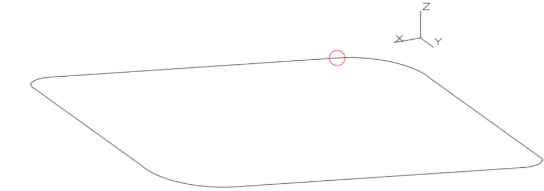
The "Elevation Editor" command is used to edit Slopes/Grades and Elevations of 3D Polylines. With this command we can convert various types of objects (entities) into 3D Polylines and edit them in the Elevation Editor. Supported input objects: 3D Polylines 2D Polylines, Polylines, Lines, Circles and Arcs.
The input object can contain of sequentially connected straight Line segments, Arc segments or a combination of both. If the "Enable Extended Polyline" is enabled, then only the start and end points of converted 3D polyline segments are displayed in a drawing. All other points that lie on the 3D Arc segments are hidden. This also allows us to move grips of individual 3D Polyline segments, including 3D Arcs. For such cases, refreshing the geometric data of the 3D polyline in the Elevation Editor is also supported.
To edit Elevations in the Elevation Editor
Click Kobi Toolkit for AutoCAD tab > Modify > Elevation Editor

Select an object in the drawing.
a. If selected object is 2D Polyline, Polyline, Line, Arc, Circle, the following option appears in the command line:
Convert selected line to 3D Polyline and edit in Elevation editor? [Yes/No] <Yes>.
Delete original line? [Yes/No] <No>.
b. If selected object is 3D Polyline, Elevation Editor dialog box opens.
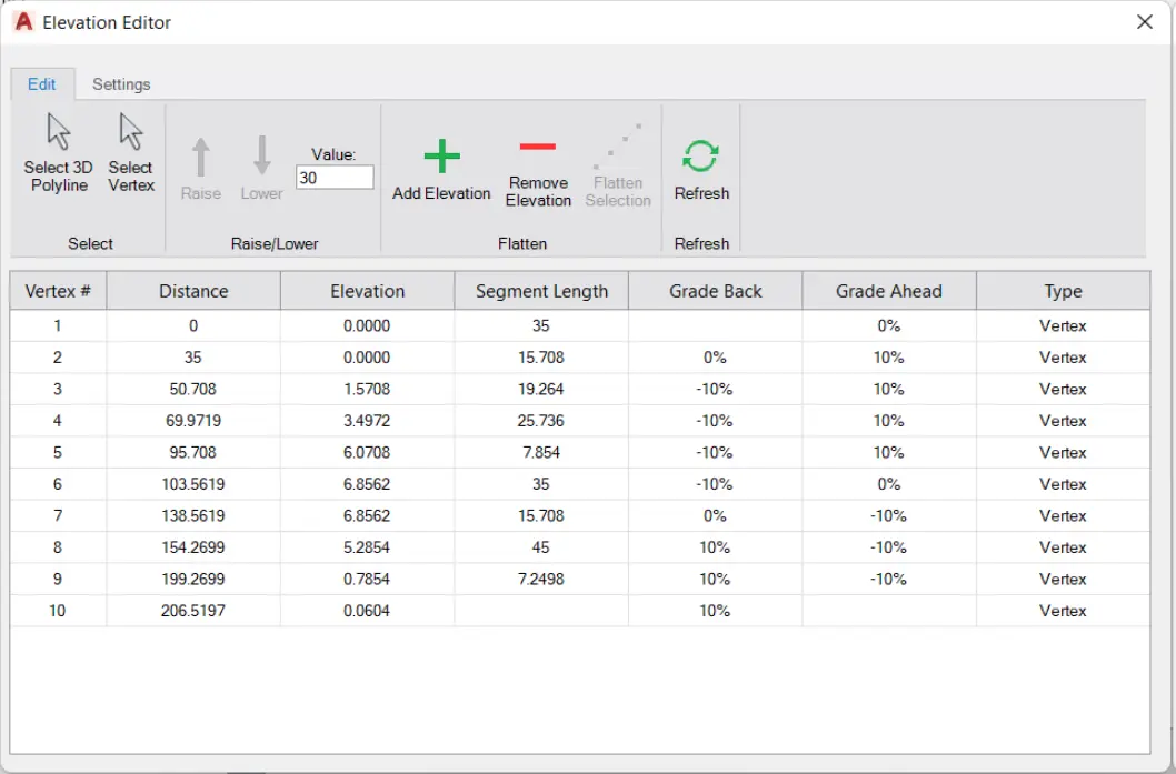
Edit tab
a. Select 3D Polyline – select input object in a drawing.
b. Select vertex – select vertices in a drawing and press Enter.
c. Raise – raise elevations of selected vertices by a specified value.
d. Lower – lower elevations of selected vertices by a specified value.
e. Value – define the step of raising/lowering elevations of selected vertices.
f. Add elevation - add elevation point on the selected position and enter its elevation.
i. New elevation point is added on straight segments of Extended 3D polyline as a new vertex.
ii. New elevation point is added on curved segment of 3D Polyline as a new elevation point.
iii. New elevation point on the curved segment is ignored, if its elevation is interpolated between the start and end point of a curve.
g. Remove elevation – remove elevation point on curved segments. Vertices on straight segments (lines) cannot be removed.
h. Flatten selection – the elevations of intermediate vertices are interpolated based on the elevations of the first and last selected vertex.
i. Refresh – refresh data in Elevation Editor dialog. Use this when element is edited outside Elevation Editor to refresh 3d polyline data.
Settings tab
a. Zoom to vertex – when checked, selected vertex is zoomed in the drawing.
b. Slope or Grade – the way of describing a slope between two vertices: Grade (%) or Slope (1: n).
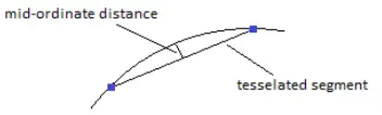
c. Max 3D Arc Tessellation – defined value is used to define number of tessellated segments of an arc.
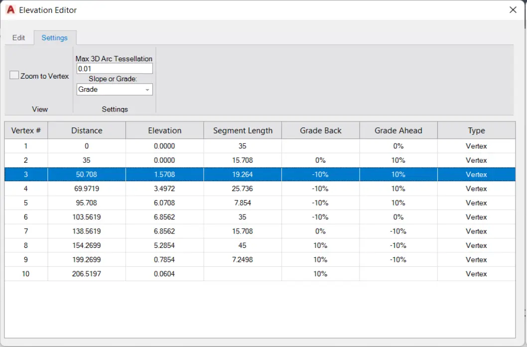
- Parameters in a table
a. Vertex # – the sequence number of the vertex on the selected 3D Polyline, similar as in Properties panel.
b. Distance – distance from the first to the current vertex.
c. Elevation – elevation of the vertex.
d. Segment Length – distance from the previous to the current vertex.
e. Grade back – slope of the segment from the currently selected vertex to the previous vertex.
f. Grade ahead – slope of the segment from the currently selected vertex to the next vertex.
g. Type – two types are possible: vertex and elevation point.
The precision of displayed measurements (in the Distance, Elevation and Segment Length columns) in Elevation Editor can be edited with the UNITS command.