# Drive
Command Description
The Drive command is used to create a new vehicle swept path analysis. After selecting a vehicle from the Vehicle Library, you define the vehicle's starting position and direction in the drawing. You then navigate the vehicle step by step through the simulation, with the ability to switch between forward and reverse driving, undo steps, and adjust various parameters in the modeless “Simulation Assistant” dialog. This dialog allows real-time control over driving speed, forward and reverse path prediction, turning radius type, and other settings during the simulation.
To create a Swept Path Analysis
- Click Kobi Swept Path tab > Create and Manage Analysis panel > Drive

Click the
 button in the Simulation Assistant dialog to open the Vehicle Library dialog, where you can select a vehicle for the simulation and click OK.
Pick vehicle position in a drawing or choose Continue to continue existing simulation.
Select vehicle direction or type it in a command line.
Pick next vehicle position or
- Reverse – Switch to reverse driving. This setting is also updated in the Simulation Assistant dialog. Choose the Forward option to switch back to forward driving.
- spiralLess – The vehicle path is calculated without considering spirals. This means that the wheels turn instantaneously at every change in direction.
- Undo – Undoes the previous step in the analysis. The Undo button is also available in the Simulation Assistant dialog.
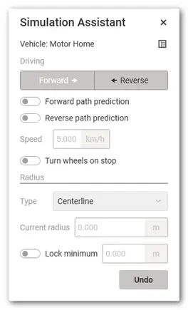
Simulation Assistant is a modeless dialog, which means you can change parameters while performing analysis in a drawing. The following settings are available:
 - switch between the Forward and Reverse driving.
- Enable / disable Forward path prediction. If you enable this option, a template will appear during the analysis, showing the predicted path the vehicle can take at the maximum steering angle while driving forward. The predicted path depends on the specified driving speed.
- Enable / disable Reverse path prediction.
- Type the driving speed.
- Enable / disable Turn wheels on stop. This setting enables the vehicle to stop and make a maximum-angle turn.
- Radius Type:
i. Centerline: Current turning radius, measured from the center of the turning circle to the centerline of the vehicle.
ii. Curb-to-curb: Current turning radius, measured from the center of the turning circle to the outer most tire.

iii. Inner-turn: Current turning radius, measured from the center of the turning circle to the innermost front wheel of a vehicle.
iv. Wall-to-wall: Current turning radius, measured from the center of the turning circle to the outermost point of the vehicle body.

- Current radius - Current turning radius, measured from the center of the turning circle to a specific point on the vehicle, depending on the selected radius type.

Lock minimum – Locks the minimum turning radius, measured from the center of the turning circle to a specific point on the vehicle, depending on the selected radius type.
Undo - undoes the previous step in the analysis.
To edit the Kobi swept path analyses
The user can create a swept path analysis either interactively by specifying vehicle positions in the drawing or by checking the maneuverability along a selected entity. At each vehicle position specified by the user in the drawing, the software creates a grip that allows the vehicle path to be repositioned. The new grip position is limited by the vehicle’s dimensions and the driving simulation parameters. If a valid path to the new position cannot be generated, the software will not allow the point to be moved there.
To edit Kobi Swept Path Entity style
Kobi Swept Path analyses are defined as custom objects, which makes them easy to copy, move, and edit using basic CAD commands. Display styles for both horizontal and vertical analyses can be configured directly in the Properties palette. You can enable or disable the display of the following analysis elements and set their display colors and hatch styles:
- outer envelope,
- outer envelope hatch,
- path,
- vehicle at a specified position,
- axle traces.
The analysis name and description can also be modified in the Properties palette. Each individual analysis in the drawing can have its own display style. When an analysis is copied, its display style is copied as well. You can define which elements of the analysis you want to display in the drawing, as well as their display style (color and hatch pattern). Each individual analysis in the drawing can have its own display style. When you copy an analysis, its display style is copied as well.
