# Settings
Command Description
This command allows you to define General Settings Templates and configure their settings individually for Horizontal and Vertical analysis, Turn Predictions, and Graph display.
To Edit General Settings Template
Click Kobi Swept Path > Create and Manage Analysis Panel > Settings
 .
.In General Settings dialog, select Metric or Imperial template from the drop-down menu.
You can configure Template settings with the
 button.
In General Settings – Template_name dialog, you can define Template's settings. This settings will be taken into account anytime when this Template is selected.
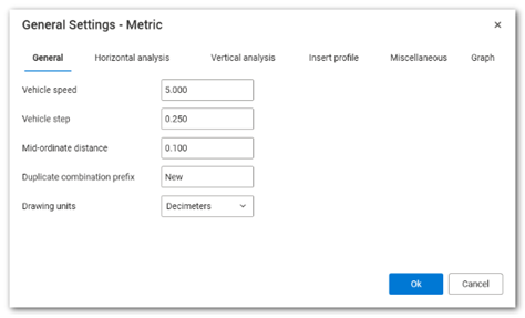
Under General tab, define Vehicle speed, Vehicle step, Mid-ordinate distance, Duplicate combination prefix and Drawing units.
Vehicle speed: The default speed value applied in the Simulation Assistant dialog when executing the Drive command to generate a new vehicle swept path analysis.
Vehicle step: Vehicle step is the small distance the vehicle moves at a time during a simulation. Smaller steps make the path more accurate and detailed.
Mid-ordinate distance: The maximum distance between the arc of a turning vehicle’s path and the chord (straight line) connecting the start and end of that arc.
Duplicate combination prefix: Prefix that is used for Vehicle name when duplicating it.
Drawing units: Defines the units in which the Swept Path analysis will be drawn. By default, the metric vehicle library is created in meters, while the imperial library is created in feet. However, the user can choose to draw vehicles - and thus the Swept Path analysis - in other units as well. For metric units, the user must select the metric template in the General Settings dialog box.
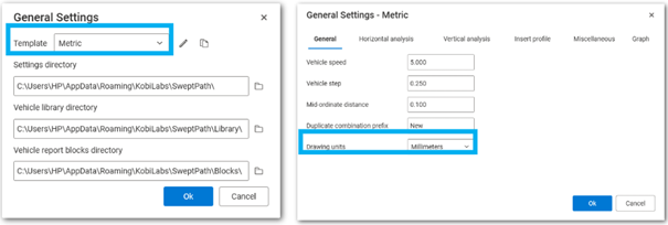
Then, the user clicks on the icon, and in the General Settings – Metric dialog box, under the General tab, selects the appropriate units from the Drawing Units section. If millimeters are selected, the vehicles will be scaled by a factor of 1000 compared to their default size in meters.
For imperial units, the user must select the imperial template in the General Settings dialog box.
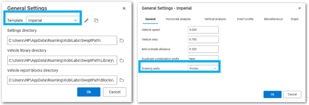
Then, the user clicks on the icon, and in the General Settings – Imperial dialog box, under the General tab, selects the appropriate units under Drawing Units. If inches are selected, the vehicles will be scaled by a factor of 12 compared to their default size in feet.
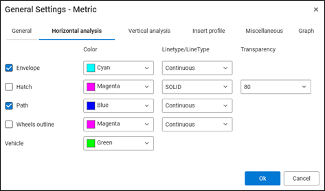
- Under Horizontal analysis tab, define parameters for Horizontal analysis.
Envelope: define the color of vehicle's envelope in the drawing.
Hatch: define the color, hatch pattern and hatch transparency for swept path analysis hatch.
Path: define the color of vehicle's path in the drawing.
Axles traces: define the color of vehicle's axles traces in the drawing.
Wheels outline: define the color of vehicle's wheels outline in the drawing.
Vehicle: define the color of the vehicle the drawing.
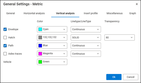
- Under Vertical analysis tab, define parameters for Vertical analysis. They are the same as in previous item.
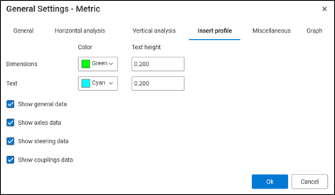
- Under Insert profile tab, define parameters for Vehicle profile.
Dimensions: define the color of vehicle dimensions and the text height.
Text: define the color of vehicle parameters listed under vehicle profile and the text height.
Show general data: check the option to show general data.
Show axles data: check the option to show axles data.
Show steering data: check the option to show steering data.
Show couplings data: check the option to show couplings data.
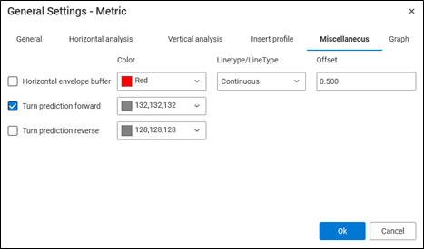
- Under Miscellaneous tab, define parameters for Turn predictions and Horizontal envelope buffer.
Horizontal envelope buffer: define the color for Horizontal envelope buffer, its linetype and the offset value.
Turn prediction forward: define the color for Turn prediction forward lines in the drawing.
Turn prediction reverse: define the color for Turn prediction reverse lines in the drawing.
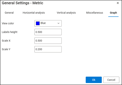
- Under Graph tab, define parameters for Graph.
View color: set the color of centerline horizontal and vertical lines of the Graph in the drawing.
Labels height: define the height of graph labels.
Scale X: defines the horizontal scaling factor applied along the X-axis. A Scale X value of 0.5 indicates that the length of horizontal elements is reduced to 50% of their original size.
Scale Y: defines the vertical scaling factor applied along the Y-axis. A Scale Y value of 0.2 indicates that the length of vertical elements is scaled to 20% of their original size.