# Conflict Detection
Command Description
The Conflict Detection command is used to analyze potential conflicts between a horizontal or vertical swept path analysis and selected entities in the drawing.
Conflicts are detected between linear CAD entities, representing curbs, edges, buildings, obstacles, or other linear geometry, and the elements of a swept path analysis.
The following linear CAD entities are supported: Line, Polyline (2D and 3D), Arc, Circle, Ellipse, Helix, Spline.
The entities used for the analysis can be selected in two ways:
Interactively, by selecting CAD entitites directly in the drawing, or
By layers, by selecting one or more layers that contain the relevant entities.
Conflict detection can be performed against the following horizontal swept path analysis elements: Vehicle Envelope, Vehicle Axle Traces, Vehicle Envelope Safety Buffer.
For vertical swept path analysis, conflict detection is available for: Vehicle Envelope, Vehicle Envelope Safety Buffer.
The results of the conflict detection are displayed only when the swept path elements used for the analysis are visible in the drawing.

If these elements are hidden, the conflicts still exist but will not be shown. This command helps identify intersections and clearance issues early in the design process, improving safety and reducing design issues.
To create a conflict detection
Click Kobi Swept Path > Report Panel > Conflict Detection
 .
.Select an existing horizontal or vertical swept path entity in a drawing.
- If a horzontal swept path enetity is selected, the following dialog opens:

- If the vertical swept path analysis is selected, the following dialog opens:

- Enable or disable Vehicle envelope. When enabled, choose how the CAD entities for conflict detection will be selected:
Click Select entities in drawing
 to select entities directly in the drawing,
Click Clear entities
 to remove all entities from the current selection set or
Click Select layers
 to choose layers in the Layer Selection dialog.

In the Layer Selection dialog you can:
Use Select All to select all layers in the drawing, or
Select individual layer checkboxes, or
Click Add from drawing
to add the layer of a selected CAD entity from the drawing.
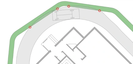
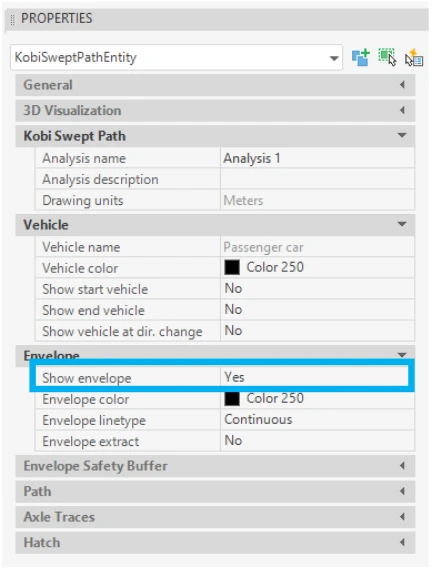
If the swept path analysis does not have the vehicle envelope displayed, select the horizontal or vertical swept path entity and set Show Envelope = Yes in the Properties panel.
- Enable or disable Vehicle axles traces. When enabled, choose how the entities for conflict detection will be selected:
Click Select entities in drawing
to select entities directly in the drawing,Click Clear entities
to remove all entities from the current selection set orClick Select layers
to choose layers in the Layer Selection dialog.
If the swept path analysis does not have the vehicle axle traces displayed, select the horizontal swept path entity and set Show axles traces = Yes in the Properties panel.

Note: For more information and a detailed description of the Layer Selection dialog, see Step 3. Enable or disable Vehicle Envelope.
- Enable or disable Vehicle envelope safety buffer. When enabled, choose how the entities for conflict detection will be selected:
Click Select entities in drawing
to select entities directly in the drawing,Click Clear entities
to remove all entities from the current selection set orClick Select layers
to choose layers in the Layer Selection dialog.
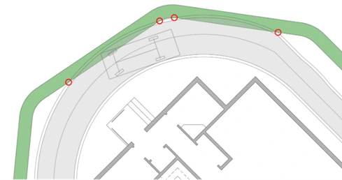
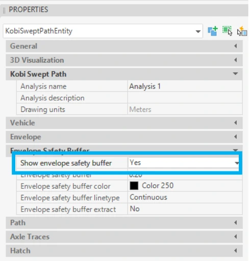
If the swept path analysis does not have the Vehicle envelope safety buffer displayed, select the horizontal or vertical swept path entity and set Show envelope safety buffer = Yes in the Properties panel.
Note: For more information and a detailed description of the Layer Selection dialog, see Step 3. Enable or disable Vehicle Envelope.