# Area Markings
Command Description
This command allows you to create and edit the Area Markings. You can create custom templates of Area Markings. In this command, the projection of Area Markings to the selected Surface is also available.
To create Area Markings
Click Kobi Signs and Stripes tab > Markings panel > Area Markings
 .
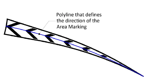
.Select closed polyline or Area Marking entity.
Select direction point P1 or select Polyline/ Arc in a drawing.
- Specify direction point P2, if direction point P1 is specified in step 3.
- Or pick Polyline/Arc entity, if the Polyline/Arc option is selected in step 3

- Select the Area Marking type from the template.
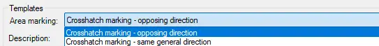
Enter the area marking description.
Optionally edit the following parameters:
- Choose between the Single (left image) and Mirrored type (right image) of Marking.

Enter an angle or click to specify it in a drawing.
Enter a Gap distance.
Enter an Offset distance.
Select an option “Fill corner” and “Fill boundary” and enter values for both parameters.
Choose the area marking color.
Enter the Label Formula. Available fields are:
<[Gap]>,
<[Width]>,
<[Offset]>,
<[Angle]>,
<[Name]>.
Select a Contour layer from the drop-down list, or type the new layer name in the field.
Select a Hatch layer from the drop-down list, or type the new layer name in the field.
Click
 to change direction point or select new Polyline/Arc entity in a drawing.
Choose the “Project to Surface” option and select a Surface from the drop-down list. Or click
 to select a TIN Surface in the drawing.
Choose the “Join into a group” option to join cross markings into a group.
Click
 for additional area marking settings:

Select a 3D projection layer from the “Projection Layer” drop-down list. Or type the new layer name in the field.
Enter the elevation of the Area Markings 3D projections above the selected Surface.
Enter the Mid ordinate distance – the precision of curves approximation with 3D Area Markings.

- Layout of fill tip – choose between the options “Use offset value” and “Do not use offset”:
o The “Use the offset value” option considers the “Offset” parameter when filling the tip, o The “Do not use offset” option fills the entire tip according to the specified “Fill corner” parameter.
- Select a Label layer from the “Projection Layer” drop-down list. Or type the new layer name in the field.
Select the “Auto preview” option to preview defined line marking in the drawing before inserting.
Click
 in the “Area Markings” dialog.
To edit Area Markings
Click Kobi Signs and Stripes tab > Markings panel > Area Markings
.Select the existing Area Marking entity.
Edit the desired parameters in the “Area Marking” dialog.
Click
to finish and close the dialog.
To work with Area Markings templates
Launch the “Area Markings” command.
Select the Area Marking entity.
The “Area Marking” dialog opens.
Select the existing Area Marking as the base from the template.
Edit the desired parameters in the “Area Marking” dialog.
Click
 to add new Area Marking to the Template. Or click
  to delete existing Area Marking from the Template.
Click
to finish and close the dialog.
