# Lane Markings
Command Description
This command allows you to create the new Lane Marking and project it to the Surface.
To create Lane Markings
- Click Kobi Signs and Stripes tab > Markings panel > Lane Markings
 .
.
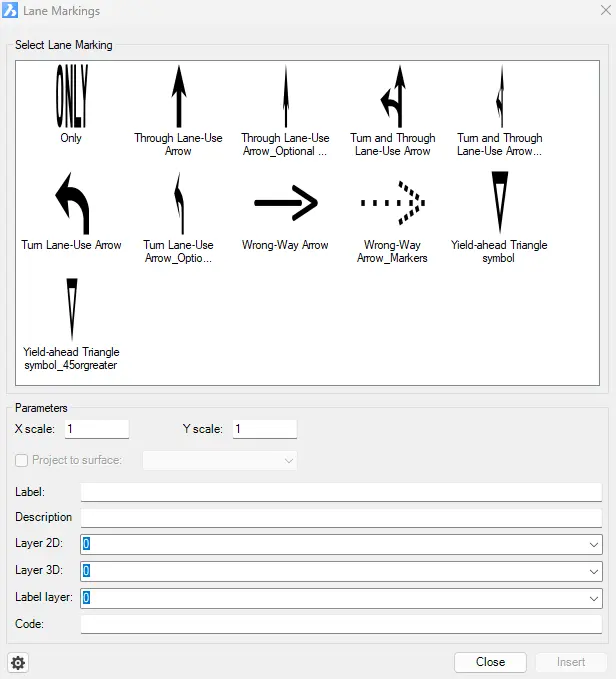
Select the appropriate Lane Marking.
Enter scale factor in the X direction.
Enter scale factor in the Y direction.
Choose the “Project to Surface” option and select a Surface from the drop-down list.
Enter the lane marking label.
Enter the lane marking description.
Select a Lane Marking Layer from the drop-down list, or type the new layer name in the field.
Click
 for additional Lane Marking settings:
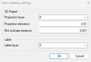
Select a 3D projection layer from the “Projection Layer” drop-down list. Or type the new layer name in the field.
Specify the elevation of the Lane Markings 3D projections above the selected Surface.
Enter the Mid ordinate distance – the precision of curves approximation with 3D Area Markings.

- Select a Label layer from the “Projection Layer” drop-down list. Or type the new layer name in the field.
- Click
 to insert lane marking.
To edit Lane Markings
Use the basic CAD commands to edit the Lane Markings: “Move”, “Scale”, “Rotate”, “Align”, etc.