# Cross Markings
Command Description
The “Cross Markings” command allows you to create and edit the Cross Markings. You can create custom templates of Cross Markings. In this command, the projection of Cross Markings to the selected Surface is also available.
To create Cross Markings
Click Kobi Signs and Stripes tab > Markings panel > Cross Markings
 .
.Press “Enter” to create new Cross Marking.
Pick base points (P1, P2, …) in the drawing.
Pick second point to determine the Cross Marking direction or choose between “Perpendicular” and “Angle”.

Select the existing Cross Marking from the template.
Optionally edit the parameters of each cross-marking item in the table: Description, Shape, Start, Length, Gap, Width, Offset, Color and Label formula. The parameters are explained on the figure in the upper section of the “Cross Marking” dialog box.
Note that available fields for the Label Formula are: • <[Start]>, • <[Length]>, • <[Gap]>, • <[Width]>, • <[Offset]>, • <[Name]>.
NOTE: By default, the marking’s IDs from Slovenian Traffic Signs Regulation are defined in “Label formula” field. Enter the “Minimal margin” – determines the minimum margin (offset) of the cross-marking item from the specified base points (P1, P2, ...). If the cross-marking items consists of rectangle and/or triangle shapes, the offset can be larger than specified, since only whole pieces of shapes are drawn.
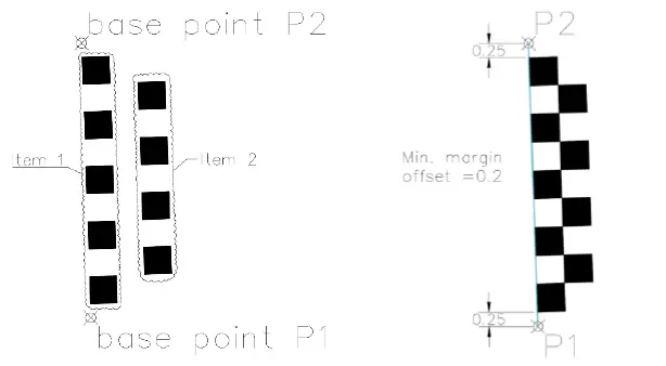
Minimal margin specified on the left image is 0.2, while actual margin offset is 0.25, since only whole pieces of rectangle shapes are drawn. Shapes are aligned By Group.
- Choose between the options to align shapes “By Group” or “By Item”.
Option “By Group” means that all margin items are aligned between the specified base points together as a one group.
Option “By Item” means that each margin’s item is aligned separately and independently of the others.
Select a Contour layer from the drop-down list, or type the new layer name in the field.
Select a Hatch layer from the drop-down list, or type the new layer name in the field.
Select the “Mirror line setting” to create a mirrored copy of the selected Cross Marking items across the specified based points (P1, P2, …).
Click
 to change positions of base points (P1, P2, …), that define the Cross Marking base line.
Click
 to change direction (angle) of Cross Marking shapes.

Choose the “Project to Surface” option and select a Surface from the drop-down list. Or click
 to select a TIN Surface in the drawing.
Choose the “Join into a group” option to join Cross Markings into a group.
Click
 for additional Cross Markings settings:

- Enter the Mid ordinate distance – the precision of curves approximation with Cross Markings 3D projection.

Select a 3D projection layer from the “Projection Layer” drop-down list. Or type the new layer name in the field.
Enter the elevation of the Cross Markings 3D projections above the selected Surface.
Select a Label layer from the “Projection Layer” drop-down list. Or type the new layer name in the field.
Select the “Auto preview” option to preview defined line marking in the drawing before inserting.
Click
 in the “Cross Markings” dialog.
To edit Cross Markings
Click Kobi Signs and Stripes tab > Markings panel > Cross Markings
.Select existing Cross Marking.
Edit the desired parameters in the “Cross Marking” dialog.
Click
to finish and close the dialog.
To work with Cross Markings templates
Launch the “Cross Markings” command.
Pick a Cross Marking entity to edit or press "ENTER" to create new.
The “Cross Marking” dialog opens.
Select the existing Cross Marking as the base from the “Cross Marking” drop-down list.
Click
 to add a new Cross Marking item and define its parameters: Description, Shape, Start, Length, Gap, Width, Offset, Color and Label formula.
Erase exiting Cross Marking item by clicking
 .
.Click
 to move the selected item up the list or
  to move it the down the list.
Click
to save a new Cross Marking template or overwrite existing one.
