# Create Grading
Command Description
The Create Grading command streamlines the grading design process by allowing users to generate grading directly from polylines, 3D polylines, and lines — without the need to select feature lines. Grading can be modeled in multiple directions, left and right, from a single baseline, with support for both sharp and rounded corners. Within one grading, users can define multiple TIN surfaces, apply advanced grading components, and utilize various daylighting options such as cut only, fill only, or a combination of both. The enhanced interface introduces features like Apply, Hide and Zoom, and Reverse Grading, while also enabling users to easily raise or lower the grading surface and efficiently manage grading criteria. New grading parameters further increase design flexibility, and overall performance and stability have been significantly improved, making the grading workflow more intuitive and capable than ever.
To create Grading
Click Kobi Toolkit for Civil 3D tab > Surfaces and Grading panel > Create Grading

Follow the instructions in the command line:
Select object to use as a footprint.
Pick start point and end point or press "Enter" button to create grading along the entire length of the footprint.
The Create Grading dialog opens.

Select predefined grading templates from drop-down menu or click
 to create new template.
Click
 if you want to delete grading
template.
if you want to delete grading
template.Click
next under grading components
section to add the first grading component.Click
if you want to remove grading
component.Click
 or
or  to move the grading component up or down the list. This allows you to change the order of grading components. The baseline (starting component) of the moved component will be updated accordingly.
Click
 to change the side of the selected grading component.
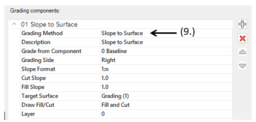
For each grading component, choose the appropriate Grading Method from the drop-down list.
Slope to Surface: Specifies that the grading projection lines will extend from the baseline (or any existing grading component) to tie into a target surface using a specified slope value. The user can define on which side of the baseline the grading will be created (right or left), and whether the grading is applied in cut only, fill only, or both conditions. Supported slope formats include 1:n, %, degrees (°), and radians (rad).
Slope to Elevation: Specifies that the grading projection lines will extend from the baseline (or any existing grading component) until they reach a specified elevation, using a defined slope value. The user can specify on which side of the baseline the grading will be created (right or left) and choose from the following slope formats: 1:n, %, degrees (°), or radians (rad).

- Slope to Relative Elevation: Specifies that the grading projection lines will extend from the baseline (or any existing grading component) until they reach an elevation defined relative to the baseline, using a specified slope value. Supported slope formats include 1:n, %, degrees (°), and radians (rad). The user can specify on which side of the baseline the grading will be created (right or left).

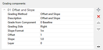
- Offset and Slope: Specifies that the grading projection lines will be extended from the baseline (or any existing grading component) until they match a specified horizontal distance (offset) using a specific slope value. Supported slope formats include 1:n, %, degrees (°), and radians (rad). The user can specify on which side of the baseline the grading will be created (right or left).
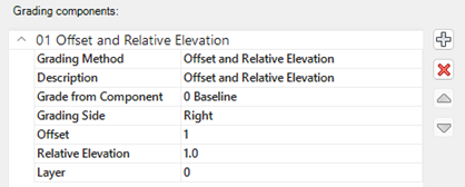
- Offset and Relative Elevation: Specifies that the grading projection lines will be extended from the baseline (or any existing grading component) until they match a specified horizontal distance and elevation relative to the baseline. The user can specify on which side of the baseline the grading will be created (right or left).
- Offset on Surface: Specifies that the grading projection lines will be moved for a specified offset (horizontal distance) and vertically projected to a target surface. The user can set a maximum allowable elevation difference between the baseline and the end point of the grading line. If the elevation difference exceeds the specified limit, the grading line will not be created.

- Drape to Surface: Specifies that the grading projection lines will be vertically projected to a specified surface.

- Surface from Grading lines: Creates Surface from specified grading components, including outer and hide boundaries.

Two triangulation methods are supported: Breaklines with rays and Breaklines only. The images below show an example with 3D stairs that have 90-degree corners. In this case, using only breaklines to create the TIN surface does not produce an appropriate 3D model.
Breaklines only:

Breaklines with Rays:

For all grading components (except "Surface from grading lines"), choose the starting grading component in the "Grade from component" field. This defines from which existing grading component the new component will start from.
Check "Draw grading transitions" in the "Create Grading" dialog to create grading with different start and end parameters. Different transitions can be applied to each grading component.
Click
 to hide the dialog and change the zoom in the drawing.
Click the Settings button
 in the "Create grading dialog" to define grading settings.

Specify the sampling interval (increment value along the footprint).
Specify Angular spacing for grading in the corners.
Specify Mid-ordinate distance for curve tessellation.
Click checkbox if you want to remove collinear points on daylight.
Click checkbox if you want to keep collinear points from source object.
From the drop-down menu select the slope format.
Click checkbox if you want to draw rays (slope lines).
Check “Enable grips” to enable editing grading with grips directly in the drawing.
Click checkbox “Group grading entities” if you want to group grading entities. After you click on grading rays or grading surface grips of all grading components are displayed.
Click
 to load a different grading template file.
After you defined everything click
 to create grading. Note that you can always add new or delete grading components in "Edit Grading" command.
Note that any changes made in the dialog are immediately displayed as a preview in the drawing.
Related commands
Edit Grading: Kobi Toolkit for Civil 3D tab > Surfaces and Grading panel > Edit Grading
Erase Grading: Kobi Toolkit for Civil 3D tab > Surfaces and Grading panel > Erase Grading
Copy Gradings: Kobi Toolkit for Civil 3D tab > Surfaces and Grading panel > Copy Gradings
Join Gradings: Kobi Toolkit for Civil 3D tab > Surfaces and Grading panel > Join Gradings
Split Grading: Kobi Toolkit for Civil 3D tab > Surfaces and Grading panel > Split Grading